Transformers

Transformers

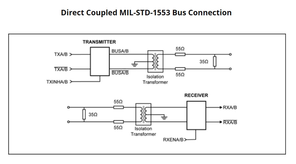
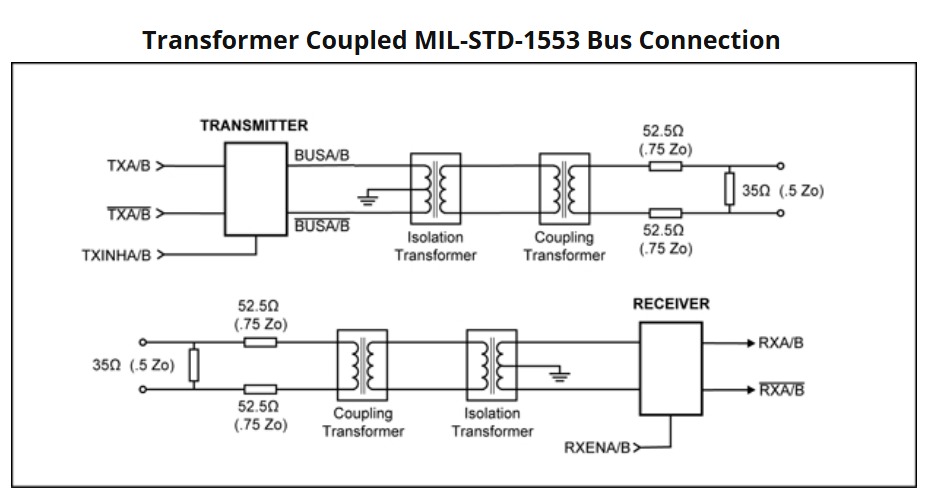
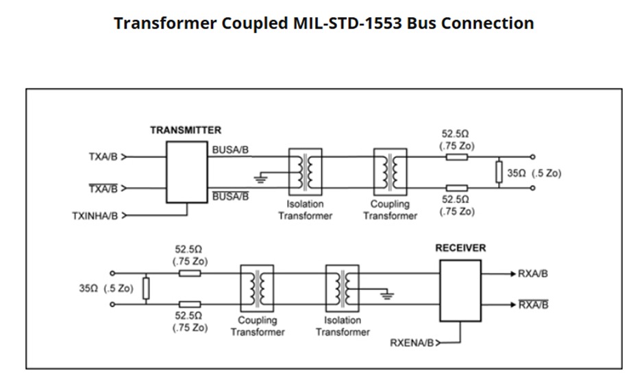
Specialised pulse transformers for MIL-STD-1553 avionics data buses. Coupling transformers provide galvanic isolation and long-stub bus coupling; isolation transformers sit within the bus controller, remote terminal, or monitor. Built to MIL-T-21038 and MIL-PRF-21038/27.

Coupling Transformers
Long-stub bus coupling

Specialised pulse transformers used to interface avionics equipment with a MIL-STD-1553 data bus. Provides galvanic isolation, protects the main bus from stub faults, and ensures impedance matching. Supports stub lengths up to 20 feet (6 metres).

§ CTCoupling transformer · designed for MIL-T-21038
Transformer turns ratio
MIL-T-21038
1 : 1.41 (±3%)
Common-mode rejection (CMR)
MIL-T-21038
> 55 dB @ 1 MHz with 10 V RMS
Open-circuit impedance (75 kHz – 1 MHz)
MIL-T-21038
|Z| > 10 kΩ min @ 25 °C
Waveform integrity (droop)
MIL-T-21038
20% max · 250 kHz square, 90 ns ±5% rise/fall
Insulation resistance — winding to winding
Ri > 1 000 MΩ @ 250 VDC
Overshoot & ringing
MIL-T-21038
±1.0 V peak · 250 kHz square, 100 ns max rise/fall
Primary DC resistance
MIL-T-21038
< 2.7 Ω
Secondary DC resistance
MIL-T-21038
< 2 Ω
Rise time
MIL-PRF-21038 · Fig 3 & 4
150 ns max
Pulse width
MIL-PRF-21038 · Fig 3 & 4
2 µs
Life expectancy “X”
MIL-PRF-21038
10 000 hours min
Dielectric withstanding voltage
MIL-STD-202 · Method 301
100 V RMS
Operating temperature
−50 °C to +125 °C
Storage temperature
−50 °C to +155 °C
Fig · Transformer-coupled MIL-STD-1553 bus connection
Transformer-coupled MIL-STD-1553 bus connection showing coupling and isolation transformers between transmitter/receiver and the bus

Isolation Transformers
Galvanic isolation

Located within the bus controller, remote terminal, or monitor. Provides galvanic isolation and signal conditioning between the terminal’s internal electronics and the external bus or stub. Standard ratios 1:1.79 and 1:1.25 — other ratios on request.

§ ITIsolation transformer · designed for MIL-T-21038
Transformer turns ratio
MIL-T-21038
1 : 1.79 or 1 : 1.25 (±3%)
Common-mode rejection (CMR)
MIL-T-21038
> 55 dB @ 1 MHz with 10 V RMS
Open-circuit impedance (75 kHz – 1 MHz)
MIL-T-21038
|Z| > 6 kΩ min @ 25 °C
Waveform integrity (droop)
MIL-T-21038
20% max · 250 kHz square, 90 ns ±5% rise/fall
Insulation resistance — winding to winding
Ri > 1 000 MΩ @ 250 VDC
Overshoot & ringing
MIL-T-21038
±1.0 V peak · 250 kHz square, 100 ns max rise/fall
Primary DC resistance
MIL-T-21038
< 1 Ω
Secondary DC resistance
MIL-T-21038
< 3.5 Ω
Rise time
MIL-PRF-21038 · Fig 3 & 4
150 ns max
Pulse width
MIL-PRF-21038 · Fig 3 & 4
2 µs
Life expectancy “X”
MIL-PRF-21038
10 000 hours min
Dielectric withstanding voltage
MIL-STD-202 · Method 301
100 V RMS
Operating temperature
−50 °C to +125 °C
Storage temperature
−50 °C to +155 °C
Fig 01 · Direct-coupled bus connection
Direct-coupled MIL-STD-1553 bus connection showing isolation transformers at the transmitter and receiver
Fig 02 · Transformer-coupled bus connection
Transformer-coupled MIL-STD-1553 bus connection showing isolation and coupling transformers
Enquiries

Request a
quotation.